OpenUPS2
11-24V Intelligent DC-DC Uninterruptible Power Supply using LiFePO4
New Feature 13-24V Intelligent DC-DC Uninterruptible Power Supply using Li-Ion (section 7.6)
Before you start…
Often times, rushing into installing the unit can result in serious damage to your OPENUPS2 board or computer. Always double check the polarity of your wires with a voltmeter.
Always double check the polarity of the batteries before introducing into the UPS device.
Improper configuration leads to system damage!!!
Use batteries from same lot, same age with same resting voltage for best results.
Introduction
The openUPS2 was designed to provide user specified regulated power output from a wide input voltage, battery backup, LiFePO4 (18650 size) battery charging and cell balancing in a single PCBA.
Battery cells are integrated in the device, no need for special cabling between cells and UPS.
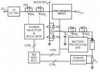
The UPS contains a synchronous boost Converter with high accuracy voltage and current regulation and automatic system power path selection from adapter or battery.
It charges the battery in three phases: preconditioning, constant current/constant voltage mode.
The unit can be used as an embedded UPS or as a Portable Energy Pack providing user regulated 12V-24V wherever is needed.
Features
openUPS2 features include:
- USB interface, works with Windows devices (Linux API planned)
- SMBUS slave
- Input between 11-24V
- Programmable voltage thresholds
- Generate any output voltage between 12-24V, booster based design
- Supports LiFePO4 (3.2V) battery chemistry
- Supports Li-Ion (3.7V) battery chemistry
- 3 state charger(precharge,constant current/constant voltage)
- Balances 3 series batteries.
- Charge voltage 3x3.5V, charge current 1A, precharge current 0.3A
- Coulomb counting
- Battery temperature monitoring for each cell and temperature compensated charging
- Start/Stop button
- Relay output
- External LED connection
- Motherboard ON/OFF pulse control*
- Missing battery cells detection
- Ultra low power consumption(1uA- in Deep Sleep mode) or (530uA- in Sleep mode)
- Windows detects device as “Battery”, no special drivers required **
- Physical dimensions
* MotherBoard ON/OFF control
The device is able to send ON/OFF 'pulse signals' to motherboard based on coulomb counter and/or battery voltage level, or based on input voltage level or when starting by button
** Windows “no driver support”
Installs itself as a battery in Windows, using the Windows hid driver without any driver installation, visible as an icon in tray bar.
Diagram & Schematics
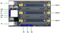
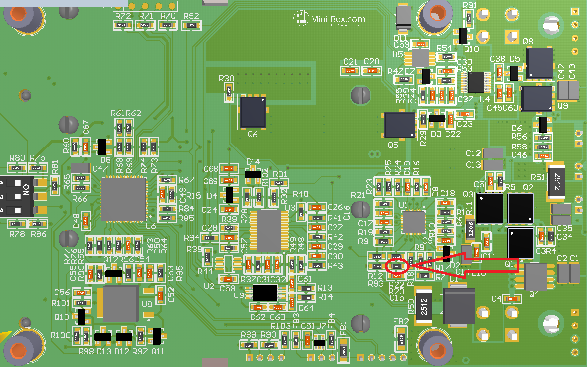
Pin1 is marked with red color.
3D Step Model - download
Connectors
Power Input connectors
- P1 Input (4pin mini-FIT JR)
- P1.1,P1.2-GND
- P1.3,P1.4-Input voltage
- P2 Output (4 pin mini-FIT JR)
- P2.1,P2.2-GND
- P2.3,P2.4-Output voltage
Interface connectors
- P3 USB header (JST PH connector, 5pin)
- P3.1: +5V
- P3.2: USB D-
- P3.3: USB D+
- P3.4: NC
- P3.5: GND
- P4 bottom side programming header, bootloader jumper, MCU reset (POGO pins)
- P4.1: nMCLR
- P4.2: GND
- P4.3: +3.3V
- P4.4: PGD
- P4.5: PGC
- P6 Motherboard POWER SW connection, no polarity (JST PH connector, 3pin)
- P6.1: SW1
- P6.2: GND
- P6.3: SW2
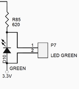
- P7 External Led header in parallel connection with D10 (JST PH connector, 2pin)
- P7.1: Cathode connection
- P7.2:+3.3V, Anode connection
- P8 SMBUS slave header (JST PH connector, 4pin)
- P8.1: +3.3V
- P8.2: SMBUS CLOCK
- P8.3: SMBUS DATA
- P8.4: GND
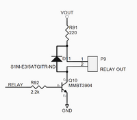
- P9 Relay output (JST PH connector, 2pin)
- P10 Start/Stop button header (JST PH connector, 2pin)
Display connectors
Bootloader Mode
It is recommended that you only connect USB power to the device
when making a firmware update via “bootloader mode”.
There are two ways to enter in bootloader mode: 1a) or 1b).
1a) Short connections between P4.4 and P4.5, than connect the unit to USB to enter bootloader mode OR
1b) Press the Enter Bootloader button on the configuration software's user interface.
2) Start the HIDBootLoader.exe software provided to flash the new firmware.
3) Press Open new Hex File for LiFePO4
or new Hex File for LiIon .
4) Locate the hex file and open it.
5) Press Program/Verify.
6) Press Reset Device.
7) After the device reconnects on USB with the configuration software the new firmware version will be displayed in the title bar of the software.
Getting started
Before you start you would need to connect the unit to USB and configure:
- Mode of Operation
- battery capacity (default is 1000mAh)
- output voltage (default is 12V)
- Low power mode (default is Sleep mode) see UPSCONFIG2 parameter for detail
- other advanced configuration parameters if needed
NOTE: After changing parameters the device needs to be restarted so the new configuration becomes active. Restart the UPS by pressing the restart button in the user configuration software. It is recommended to disconnect large loads at the output of the UPS before pressing the restart button on the user interface.
Warning: Improper configuration (ex: wrong under-voltage, over-voltage), reverse polarity can lead to battery damage or your system damage (ex: wrong output value)
UPS Configuration
The UPS can behave differently depending on settings. The OPENUPSMODE parameter sets this behaviour.
0-Autorestart when input is present=yes 	(UPS)
1-Autorestart when input is present=no	   	(LAPTOP)
2-Energy Pack mode			   	(ON/OFF)
Mode 0 and 1
- When using the UPS embedded in a system together with a motherboard the modes 0 and 1 should be used.
- Connect USB header P3 to the motherboard's internal USB header. USB connection is used to sense the motherboard's ON or OFF state.
- Connect P6 header's 1 and 3 pins to the motherboard's POWER SW header. (cable provided). Connect P10 header to a push button. This push button completely eliminates the need for any additional buttons to start or stop your system.
- Starting your system
- Mode 0 - when adapter input voltage is present a momentary pulse is sent through P6 header starting your system immediately.
- Mode 1 - the momentary pulse is not sent and your system will not be started but battery charging is possible just like in a laptop.
Mode 2
- In this mode the UPS can be a portable energy pack. Shutting down the UPS does not depend on USB connection. With the use of a push button connected to the P10 header you can instantly start and stop the UPS's output when running on battery. Connecting input power will charge the pack just like in any other modes. It also acts as an UPS providing uninterrupted output in this mode. This mode is recommended for powering devices other than motherboards or for portable energy use when working on the field and regulated 12-24V power is needed from batteries.
- Stopping your system
- When your system is up and running you can always stop it by pressing again on the push button or by shutting down from the OS(Operating System).
In case your system is on battery and under-voltage situation is present it will be automatically shut down. - When the system is on battery and it is shut down by OS the UPS can also immediately shut down to preserve battery. This is a configurable feature.
- When the UPS runs on batteries for a predefined time can initiate a shut down sequence. This is configurable feature.
NOTES:
- When the UPS is shutting down it senses the motherboard's state by measuring the +5VUSB signal.
  If the motherboard was shut down by the OS (+5VUSB is not present) no pulse will be sent.
- When shutting down from battery If the OS does not graciously shut down during
  predetermined UPS_HARDOFF_TOUT (60s by default) the motherboard will be forced off
  by turning off the UPS's output in order to conserve the battery.
Output configuration
There are two ways of setting the output voltage.
1)If bit0 in UPS_CONFIG parameter is set to '1' the output value is set by the OUT_VOLTAGE parameter.(default is 12V)
2)If bit0 in UPS_CONFIG is set to '0' the the output value is set by the configuration switch P5 on the back side of the unit.
- The hardcoded values depending the switches position are:
| P5.1 | P5.2 | P5.3 | OUTPUT[V] |
| OFF | OFF | OFF | 12V |
| OFF | OFF | ON | 13.5V |
| OFF | ON | OFF | 15V |
| OFF | ON | ON | 16V |
| ON | OFF | OFF | 18V |
| ON | OFF | ON | 19V |
| ON | ON | OFF | 21V |
| ON | ON | ON | 24V |
The second method is useful when using the UPS in Mode 2 as a Portable Energy Pack on the field to configure the required output voltage.
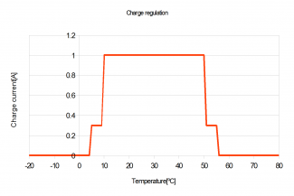
Temperature compensated charge current regulation
- The temperature threshold parameters can be adjusted from software.
- The configurable parameters are: CHG_TEMP_COLD < CHG_TEMP_COOL < CHG_TEMP_WARM < CHG_TEMP_HOT.
Setting Power plans under Windows Operating Systems (Vista, Windows 7)
- 1) Right click on the battery icon from the tray bar then choose power options from the context menu. Alternatively you can choose Power Option also from Control Panel Items.
- 2) Select/Create a power plan or modify existing ones.
- 3) In the Change Advanced Power Settings section, the critical and low battery levels and actions can be also modified
NEW FEATURE, Configuring OPENUPS2 to work with Li-ION 3.7V
- Recomended input power supply should provide >=13V and capable of providing at least 1A for charging + the current needed to sustain the required output power. Using a 12V power supply is not recomended for Li-ION since the input would be close to battery voltage or lower and the batteries can't be charged enough and the system will run mostly on batteries.
- PCB changes:
- Resistor R20 should be changed to 576k, charge voltage is set to 12.168V (3x4.056V)
- Proposed part number and description: RES 576K OHM 1/10W 1% 0603 SMD
- http://www.digikey.com/product-detail/en/RC0603FR-07576KL/311-576KHRTR-ND/727311
- Firmware and parameter changes:
- Update the device with Li-Ion version of firmware which includes support for Li-Ion chemistry!
- It can be downloaded from [1]
- The default parameters for Li-Ion are as below:
- UPS_VCELL_MIN_START =3.6V
- UPS_VCELL_MIN_STOP =3.3V
- UPS_VCELL_MIN_HARD_STOP=3V
- CHG_VCOND=3.3V
- CHG_BULK_STOP_VOLTAGE= 4.1V
- CHG_START_VOLTAGE=3.85V
- CHG_GLOBAL_TOUT=240
- BAL_VCELL_MIN=3.4V
- CAPACITY=2400mAH, should be changed to match the cell's capacity
- OCV_SOC0=3.3V
- OCV_SOC10=3.68V
- OCV_SOC25=3.76V
- OCV_SOC50=3.82V
- OCV_SOC75=3.97V
- OCV_SOC100=4.17V
- Feel free to adjust these parameters if needed
Connecting DC input power
Connect a proper input voltage source to the P1 connector.
If input voltage is present , the UPS will enable the proper power path and energy will be flowing from input to output and, if necessary, battery charging is started.
A gratuitous pulse is sent through P6 to wake up the motherboard depending configured Mode.
Each cell is carefully monitored so that in case of an under-voltage or over-voltage event proper actions are taken.
The charger is a BUCK converter so in order to charge batteries input voltage should be higher than battery voltage.
Blink modes
Status of Main LED(green)
- -Steady ON: UPS is on Input Power
- -ON for 0.5sec,OFF for 2.5sec: UPS is Battery Powered
- -Blinking On/OFF every 2 sec : OFFDELAY
- -3 fast blinks and pause repeated every 2 seconds: HARDOFF delay
- -Steady OFF:UPS is in ship mode
- -high frequency blinking: battery cell is missing(cell voltage is less than 100mV)
Status of Battery LED(red)
- -Steady ON: UPS is Battery Powered
- -Steady OFF: Battery is not being charged
- -Blinking On/OFF every 2 sec: Battery is being charged
- All LEDs OFF
- Unit is in Ship mode consuming less than 1uA. MCU is not powered. Can be waked up by pressing P10 or if input voltage is present.
Fuel gauge
The initial remaining capacity is detected based on an open-circuit voltage based state-of-charge estimation, using the predefined values set by the OCV_SOCxx parameters.
Further estimation is based on coulomb counting method which is more precise after a full charge cycle has been performed.
The UPS doesn't save the coulomb counter in its internal flash memory when it is shut down.
After wakeup the open-circuit voltage based estimation is used again.
Characteristics
Minimum Input Operating voltage
Maximum input Operating voltage
Deep-Discharge shutdown threshold
Deep Sleep(Ship mode) Current Consumption
Sleep mode Current Consumption
Storage and operating temperature
MTBF
Input connectors
Output Connector
11V
24V
configurable
< 1uA, see UPS_CONFIG2 parameter for detail
530uA, see UPS_CONFIG2 parameter for detail
-40oC to +85oC (storage), -40oC to +65oC (operating)
50K Hrs @ 85oC, >= 200K Hrs at 65oC (projected)
Mini-Fit JR
Mini-Fit JR
Output/Input Rail Output Current (buck/boost converter)
Maximum input current: 5A(consult with battery manufacturer for ratings)
Peak Input current: 6A(<30 seconds)
Maximum output current: 5A (input current dependent)
Peak output Current: 6A(<30 seconds)
NOTE:
When operating at high voltage (input or output) or/or operating at elevated temperatures
de-rating up to 30% might be necessary, forced ventilation required.
For long life operation, please ensure that hottest component on-board is kept below 65C.
Output Booster measurements
Support and warranty
Standard Hardware Warranty 1Year / US, 2 Year EU.
Parameter List
| NAME | Description |
|---|---|
| OPENUPSMODE | OPENUPS mode 0-Autorestart when input is present=yes (UPS) 1-Autorestart when input is present=no (LAPTOP) 2-Energy Pack mode (ON/OFF) |
| CAPACITY[mAh] |
Battery Capacity |
| MOB_ONOFF_TOUT[ms] |
The power switch on the motherboard(if connected) will be shorted this period to turn the Motherboard ON or OFF. |
| UPS_BUTTON_ON_TOUT[ms] |
The pushbutton connected on the P10 header must be shorted this period to be considered as pressed. |
| UPS_CONFIG[bit7..bit0] |
Configuration register. Used for enabling disabling modules.0-disabled;1-enabled |
| UPS_CONFIG2[bit7..bit0] |
Configuration register.Used for enabling disabling modules.0-disabled;1-enabled 01: Sleep mode CPU OFF (530uA) 10: Ship mode CPU OFF(1uA) 11 or 00: Standby mode CPU ON(15mA) ==> Ship mode CPU OFF(1uA) |
| UPS_VIN_MIN_START [V] |
If input voltage is above this threshold the UPS will start and take power from the input. |
| UPS_VCELL_MIN_START [V] |
If Vin is not present and all the battery cells are above this threshold the UPS can start and runs on battery
Default is 3V. |
| UPS_VCELL_MIN_STOP [V] |
If VIN is not present and one of the battery cells is less than this threshold during the time period specified by UPS_VBAT_UVP_OFF_TOUT parameter the UPS will initiate shut down procedure. |
| UPS_VCELL_MIN_HARD_STOP [V] |
If VIN is not present and one of the battery cells is less than this threshold the UPS will instantly shut down to preserve battery. |
| UPS_VBAT_UVP_OFF_TOUT [s] |
During this period battery cells are checked against UPS_VCELL_MIN_STOP. If cell voltage exceeds UPS_VCELL_MIN_STOP the timer is rearmed so it can filter unwanted noise in the system. |
| UPS_HARDOFF_TOUT[s] |
After UPS_VBAT_UVP_OFF_TOUT passed motherboard is signaled to shut down. The UPS will wait this period so that the Motherboard can shut down gracefully, than cut power and enter deep sleep. This period should not be too long to prevent battery drain. |
| UPS_VBAT_SLEEP_TOUT[s] |
Deep sleep timeout..If system is running on battery and this period has elapsed with no input power applied, then the UPS will initiate shut down procedure. "Never" is allowed as value (to disable this feature). |
| DCHG_IMAX[A] |
Max allowed discharge current. In case discharge current exceeds this threshold shutdown will be initiated. |
| CHG_VCOND[V] |
Conditioning/Pre-charge voltage. Charge current is limited until cell voltage exceeds this value and for at least
CHG_TCOND time . |
| CHG_TCOND[V] |
Conditioning/Precharge time. Charge current is limited until cell voltage exceeds CHG_VCOND value and it is applied during this time. |
| CHG_BULK_STOP_VOLTAGE[V/cell] |
Maximum allowed bulk charge voltage/cell during constant current/constant voltage charging. |
| CHG_HYSTERESIS[V/cell] |
An over-voltage value (CHG_BULK_STOP_VOLTAGE+CHG_HYSTERESIS ) that it is allowed when charging. If one of the cells exceeds this value charging is immediately stopped. |
| CHG_START_VOLTAGE [V/cell] |
If cell voltage is below this value charging can be started. |
| CHG_GLOBAL_TOUT[min] |
Global charge timeout. |
| CHG_TOPPING_TIMER[s] |
For Lithium based batteries after an overvoltage condition is detected for a cell a resting period is set by this timer before applying a small topping charge in case other cells are still not charged. |
| CHG_BAT_TYPE |
The battery chemistry to be charged. |
| CHG_TEMP_COLD[°C] |
COLD temperature treshold for temperature compensated charge current regulation. |
| CHG_TEMP_COOL[°C] |
COOL temperature treshold for temperature compensated charge current regulation. |
| CHG_TEMP_WARM[°C] |
WARM temperature treshold for temperature compensated charge current regulation. |
| CHG_TEMP_HOT[°C] |
HOT temperature treshold for temperature compensated charge current regulation. |
| BAL_VCELL_MIN[V] |
Balancing is allowed if cell voltages are above this value. |
| BAL_VCELL_DIFF_START [V] |
If the voltage difference between cells exceeds this value start balancing the cells. |
| BAL_VCELL_DIFF_STOP[V] |
If the voltage difference between cells is less than this value stop balancing the cells. |
| OUT_VOLTAGE[V] |
The output voltage. Bit0 in UPS_CONFIG parameter should be set to “1” in order this parameter has effect. |
| OUT_MAX_REGULATOR_STEP[steps] |
Maximum allowed regulation step number for output module (0-255) |
| OUT_FOLLOW_OFFSET[V] |
Offset for adaptive output regulation. |
| OCV_SOC0[V] |
Open Circuit Voltage State Of Charge detection for initial 0% fuel gauge estimation. |
| OCV_SOC10[V] |
Open Circuit Voltage State Of Charge detection for initial 10% fuel gauge estimation. |
| OCV_SOC25[V] |
Open Circuit Voltage State Of Charge detection for initial 25% fuel gauge estimation. |
| OCV_SOC50[V] |
Open Circuit Voltage State Of Charge detection for initial 50% fuel gauge estimation. |
| OCV_SOC75[V] |
Open Circuit Voltage State Of Charge detection for initial 75% fuel gauge estimation. |
| OCV_SOC100[V] |
Open Circuit Voltage State Of Charge detection for initial 100% fuel gauge estimation. |
| AFE_OLV[-] |
Advanced parameter. |
| AFE_OLD[-] |
Advanced parameter. |
| AFE_SCC[-] |
Advanced parameter. |
| AFE_SCD[-] |
Advanced parameter. |
| WRITE_COUNT[cycle] |
Number of times the flash memory has been written. Parameter is Read only. |
Software manual
Windows OS built-in support
The OpenUPS implements two generic USB classes, therefore most of the operating systems are recognizing it without any additional driver installation. This two classes are:
a.) "HID UPS Battery" for OS built-in communication.
Microsoft Windows versions are recognizing this class automatically and the device should appear in device manager at Batteries as a "Hid ups battery", together with all settings and power plan possibilities provided by the OS for any battery.
b.) "HID" for communication and configuration
This endpoint is a generic HID and it is used by our configuration and monitor softwares to read/write voltages and other important parameters of the OpenUPS2
Configuration software
The configuration software provides interface for OpenUPS2 monitoring, logging and setup.
It's recommended to be used by users with deeper understanding of the OpenUPS2 hardware since permits setting voltages, currents and other parameters which can be
dangerous if they are set without precaution.
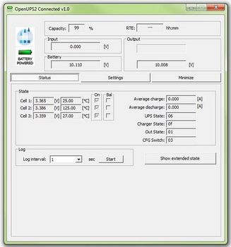
The configuration software has two main screens (Status and Settings) and a header with the important voltage/current values.
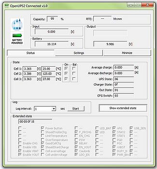
The first main screen is the "Status"
Examples of this screen is shown in the next images:
The title bar shows the connection status and the firmware version of the OpenUPS2. Example: "OpenUPS2 Connected v1.0"
The header of the status screen contains:
- Two icons:
- The upper one is the Mini-box.com logo and it does not changes.
- The second icon is present only when OpenUPS2 is connected to the UPS and can be "Battery powered" (like int the example screenshots), "Line powered" and "USB powered". It displays the state of the OpenUPS2
- Capacity: shows the remaining capacity of the batteries
- RTE: run time to empty
- Input: input voltage applied to the OpenUPS2 (P1 Input)
- Battery: battery voltage
- Output: output voltage of the OpenUPS2 (P2 Output)
The "Status" screen contains extended information about the current state of the OpenUPS2 like battery voltages, charge/discharge currents, temperature/voltage of the batteries and different states. The user also have the possibility to log the current state into a *.csv file. The "Extended state" flags are for debug/support and can change between different firmware versions.
The second main screen is the "Settings"
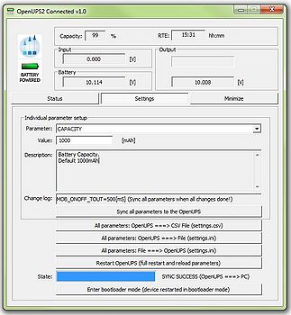
Example of this screen is shown in the next image:
This screen contains two main sections: the individual parameter setup for experienced users and the parameter save/load into/from file section.
IMPORTANT: any parameter setting or battery wizard data is taken into account by the OpenUPS2 only after a full restart either with power cut from all sources (usb, battery, vin), either by the "Restart OpenUPS (full restart and reload parameters)" button. Do this with precaution, check the parameters and wires before doing it!
The main section of the "Settings" screen is the individual parameter settings.
This is recommended to be done only by experienced users. Any parameter of the OpenUPS2 can be set from here.
Changing one parameter is simple:
- - select the desired parameter from the "Parameters" drop down menu. The current value is displayed in the "Value" field together with the unit ([V], [mA] etc.).
- - introduce the new value
- - the introduced value is checked whenever you change the current selection for the "Parameters" or choose to sync with "Sync all parameters to the OpenUPS". If the
result of the check is correct, the resulting value is shown in the "Change log" field, otherwise error message might be popped up and the parameters selector jumps back to the wrong value.
- - after You have done with all parameter setting press the "Sync all parameters to the OpenUPS" button to send all values to the OpenUPS2.
IMPORTANT: without this step the new values will be lost, nothing is sent to the OpenUPS2!
For users who need to setup more devices with the same OpenUPS2 settings, it is recommended to use the save/load parameters buttons. The "All parameters: OpenUPS ===> File (settings.ini)" button loads a full configuration from the OpenUPS and saves it to the settings.ini file. You can disconnect the current OpenUPS2 from the USB and insert a new one, than press the "All parameters: File ===> OpenUPS (settings.ini)" button to send the last saved configuration into the new OpenUPS2.
The "All parameters: OpenUPS ===> CSV File (settings.csv)" button loads all parameters from the connected OpenUPS2 and saves it into a csv file. This type of file can be opened by any spreadsheet editor (OpenOffice, Microsoft Excel etc.) and contains the full set of parameters in human readable form.
The "Enter bootloader mode (device restarted in bootloader mode)" button is intended to be used for firmware updates. After You press this button the OpenUPS2 will disconnect, it will switch to bootloader mode and firmware can be updated as described here
Every save/load/sync operation on the "Settings" screen affects the progress bar and the status bar on the bottom of the screen (labelled with "State:"). In rare cases You might get error here with "try again" message. This happens in case of one parameter byte get's corrupted or timeout occurs during USB communication and/or OpenUPS flashing operation. Please try again and contact our support team only if the device gives this error 4-5 times in a row.
Windows System monitor
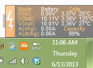
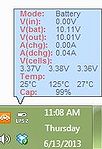
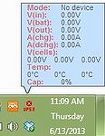
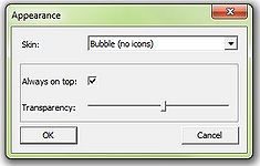
The system monitor is a tray bar software which shows the current state on the tray bar icon and a semi transparent "always on top" capable small window.
The popup window can be moved anywhere on the screen and can be customised. Our current setup has two skins but any combination is possible playing with the
"skin*.mbs" files installed together with this application. The current skin can be selected right clicking on the try icon.
The "skin*.mbs" files are simple text ones editable with any text editor (notepad for example).
Adding a new skin is pretty simple – make a skin2.mbs (use the existing skin0.mbs or skin1.mbs for starting content) and start playing with the values from the new
file.
The values are self explanatory – skin name, background image files, font descriptions and label/value pair coordinates for all the important OpenUPS2 values.
The size of the popup is defined by the background image – transparent parts can be defined as well (see for example: "bubble1.bmp").
Example screenshots:
Developer manual
Mini-box.com provides one OpenUPS2 API in a DLL (OpenUPS2Lib.dll) and examples in Visual C++, Visual Basic and Visual C#.
Basic C++/Visual Basic/C# knowledge is needed to use this examples together with the API.
The API dll has manifest embedded to permit C# and Visual Basic dynamic load, external manifest is also provided in case if it is needed.
The API has a set of functions exported to access the full functionality of the OpenUPS2.
This functions are:
- unsigned char upsOpenDeviceHandler(unsigned int timer); //open device handler. timer sets the refresh period in milliseconds (4 messages will be sent in this period), don't use values lower than 40msec here (cpu usage and usb traffic will increase with lower values). IMPORTANT: the handler can be kept open to notice any OpenUPS2 plugged in
- void upsCloseDeviceHandler();//close device handler
- void getUPSDevicePath(char* path);//get device path
- unsigned char isUPSConnected();//0=not connected, 1=normal state,2=loading settings from device,3=saving settings from pc,4=saving settings from file
- float getUPSVIN();//UPS Voltage IN
- float getUPSVBat();//UPS Voltage Battery
- float getUPSVOut();//UPS Voltage out
- float getUPSCCharge();//UPS charge current
- float getUPSCDischarge();//UPS discharge current
- float getUPSVDuty();//duty cycle
- float getUPSVCell(int i);//cell voltages (i=0,1,2)
- float getUPSTemperature(int i);//cell temperatures (i=0,1,2)
- unsigned char getUPSVerMajor();//firmware version major number
- unsigned char getUPSVerMinor();//firmware version minor number
- unsigned char getUPSState();//ups state (0=disconnnected, 1=running from battery, 2=running from VIn, 3=running from USB)
- unsigned char getUPSRemainingCapacity();//remaining capacity
- unsigned char getUPSVOutPot();//voltage out regulator %
- unsigned char getUPSConfigSwitch();//config switch/debug info
- unsigned char getUPSStateByteUPS();//state byte/debug info
- unsigned char getUPSStateByteCHG();//charger state/debug info
- unsigned char getUPSStateByteDBG();//debug byte
- unsigned char getUPSBatteryOn(int i);//battery connected (i=0,1,2)
- unsigned int getUPSRTE();//Remaining time to empty
- unsigned char getUPSMode();//mode byte/reserved
- unsigned char getUPSDbgByte(int i);//more debug bytes
- unsigned char getUPSDbg2Byte(int i);//even more debug bytes
- unsigned char getUPSCheck23(int i);//extended state flags/debug info
- unsigned char getUPSCheck24(int i);//extended state flags/debug info
- unsigned char getUPSCheck25(int i);//extended state flags/debug info
- void restartUPS();//restart ups and reload parameters
- void restartUPSInBootloaderMode();//restart ups into bootloader mode (for updating fimware)
- void setUPSCommand1Byte(unsigned char command, unsigned char value);//debug states/reserved
- void setUPSCommand2Byte(unsigned char command, unsigned int value);//debug states/reserved
- void incDecVOutVolatile(unsigned char inc);//dynamically increase/decrease voltage (not saved into parameters for next startup)
- void setVOutVolatile(float vout);//directly set voltage (not saved into parameters for next startup)
- unsigned int getUPSMaxVariableCnt();//return variable count of the OpenUPS2
- unsigned char getUPSVariableData(unsigned int cnt, char* name, char* value, char* unit, char* comment);//get name, value, measuring unit and explication by variable index
- void startUPSLoadingSettings(unsigned char to_file, unsigned char compare_with_old);//start to load settings from device
- unsigned char getUPSLoadingSettingsState();//load settings state: 0-64 - steps, 100=success, 0xF1-0xFF=failure/errorcode
- unsigned char setUPSVariableData(unsigned int cnt, char* value);//set individual variable by index (string form, permitted values described in hardware manual)
- void startUPSSaveSettings(unsigned char from_file);//start saving parameters into device
- unsigned char getUPSSaveSettingsState();//saving state: 0-64 - steps, 100=success, 0xF1-0xFF=failure/errorcode
See the examples for usage.
IMPORTANT: the API dll needs 4 files from Visual Studio 2005 redistribution pack (Microsoft.VC80.CRT.manifest, msvcm80.dll, msvcp80.dll, msvcr80.dll).
IMPORTANT: the API supports only one OpenUPS2 connected to the computer.
Visual C++ Example
Open CLibTest.sln from the package, run it and see CLibTest.cpp for usage example.
Visual Basic Example
Open VBLibTest.sln from the package, run it and see Module1.vb for usage example.
Visual C# Example
Open CSLibTest.sln from the package, run it and see Program.cs for usage example.
