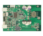
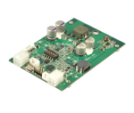
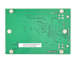
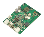
DCDC-NUC
6-48V Intelligent Automotive grade Power Supply
Introduction
The DCDC-NUC was designed to provide user specified(+12V or +19V) regulated power output from a wide input voltage(6V-48V). Default output setting is set to +12V.
It has a range of intelligent functions not found in any traditional USB DC-DC converters.
The unit is able to send ON/OFF ‘pulse signals’ to motherboards based on filtered input voltage levels or Ignition sensing, making it an ideal device for automotive or battery powered installations.
Two main modes of operation are possible:DUMB and AUTOMOTIVE.
The output voltage setting (12V or 19V) can be changed through the
Configuration switches .
The configuration switches can also be used to enter bootloader mode for updating firmware which is detailed in Bootloader Mode section.
More advanced parameters are detailed in the Parameter list which can be configured using the Configuration Software.
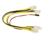
Product images
Features
- Input between 6V-48V
- Programmable voltage thresholds
- Selectable output voltage(+12V,+19V)
- Anti Thump output in automotive mode
- Motherboard startup/shutdown control by ON/OFF pulse
- Motherboard shutdown control by USB
- Highly customizable startup/shutdown timers
- Low Power consumption
- HID-USB connection
- Input, Output Voltage and Current measurement
- Temperature measurement
- Motherboard detection using output Power measurements or 5V USB
- Programmable Spread Frequency Modulation for reduced EMI
- Physical dimensions
Operating modes
The operating modes can be selected by setting the NUCMODE parameter to 0(DUMB mode) or 1(AUTOMOTIVE mode) using the Configuration Software. The default setting is AUTOMOTIVE.
For basic operation, you would need to connect a power source to the input connector. Polarity is marked on the PCB. See Diagram & Schematics section for further details
Without any further settings if the input conditions are satisfied the unit will generate +12V regulated.
Further parameters can be customized by changing in the Parameter List.
For configuration or firmware update USB connection is sufficient.
Dumb Mode
- Starting the unit
- In this mode starting can be performed by applying an input voltage higher than the value set by the VIN_MIN_STARTUP parameter.In order to filter out unwanted noise the input voltage should be higher than this threshold for the duration set by the VIN_COUNT parameter.
- 12V output and Thump output will be activated.
- After output is ON and a timeout elapses set by the MOB_PULSE_TOUT parameter, the motherboard will be pulsed with a 500ms pulse set by the MOB_PULSEWIDTH parameter.
- Stopping the unit
- During ON state output will be only turned OFF immediately if the filtered input voltage becomes less than the threshold set by the VIN_MIN_RUNNING parameter.
Automotive Mode
- Starting the unit
- In this mode Starting can be performed by applying input voltage higher than the value set by the VIN_MIN_STARTUP parameter and applying ignition voltage higher than the IGN_HIGH_THRESHOLD parameter.
- The input voltage should be higher than VIN_MIN_STARTUP for the duration set by the VIN_COUNT parameter.
- The Ignition voltage must be higher than IGN_HIGH_THRESHOLD for the duration set by the IGN_COUNT parameter in order to filter out unwanted noise in automotive environment.
- After Ignition is considered ON output will be turned ON after IGN_ON_TO_OUTPUT_ON_TOUT elapses.
- 12V output will be activated. Thump output will be activated after timeout elapses set by the THUMP_TOUT parameter.
- After output is ON and a timeout elapses set by the MOB_PULSE_TOUT parameter, the motherboard will be pulsed with a 500ms pulse set by the MOB_PULSEWIDTH parameter.
- Stopping the unit
- During ON state output will be only turned OFF immediately if the filtered input voltage becomes less than the threshold set by the VIN_MIN_RUNNING parameter.
- If Ignition voltage becomes lower than IGN_LOW_THRESHOLD and Ignition canceling is over (set by the IGN_CANCEL_TOUT parameter) a shutdown sequence will be initiated
- If Ignition is considered OFF the motherboard is pulsed for shutdown after IGN_OFF_TO_MOB_PULSE_OFF_TOUT elapses.
- After the HARD_OFF_TOUT timeout elapses the output will be turned OFF and the unit will enter in a low power state.
Motherboard control
The following options are available to control the motherboard by pulsing the on/off pins on the motherboard.
First the the motherboard on/off pins should be connected to the P4.1,P4.3 pin on the P4 Interface_connector.
The pulse width is 500ms by default which can be altered by changing MOB_PULSEWIDTH parameter from the Parameter_List.
There are various ways to control the motherboard depending the configuration of the CONFIG1 register from the Parameter_List.
Example:If startup of the motherboard is not needed when input is present, the startup pulse can be disabled by setting CONFIG1.b1 to 0.
The same way the shutdown pulse can be inhibited by setting CONFIG1.b2 to 0.
There are cases when motherboard started(ON) or OFF presence must be detected in order starting/stopping by pulses behavior work properly.
For example the Operating System could be shutdown already from software. In case the unit is is a shutdown sequence not knowing this piece of information would lead by sending the shutdown pulse which would wake up instead the system.
There are two kinds of feedback information to detect motherboard status.
The first detection mode is by measuring the consumed output power, knowing that a motherboard when started consumes much more power than when in standby.
In order to enable this feature the following steps should be performed:
1. Enable this feature, CONFIG1.b3 should be set to 1.
2. Observe and note the consumption of the connected motherboard when in standby and when is ON.
Our unit measures the output power(POUT) which is displayed in the configuration software.
3. Set POUT_HIGH_THRESHOLD and POUT_LOW_THRESHOLD parameters from the Parameter_List accordingly with a good margin.
POUT<POUT_LOW_THRESHOLD motherboard is considered OFF.
POUT>POUT_HIGH_THRESHOLD motherboard is considered ON.
The second detection mode is by measuring the +5VUSB signal. Usually motherboards turn OFF the +5VUSB signal when they are OFF.
In order to enable this feature CONFIG1.b5 must be set to 1.
If CONFIG1.b4 set, the PSU can shut down the OS by sending a Power Button event on USB.
Diagram & Schematics
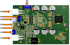
Connectors
Power Input connectors
- P1 Output (4pin mini-FIT JR)
- P1.1, P1.2 - GND
- P1.3, P1.4 - Output voltage
- P2 Input (4pin mini-FIT JR)
- P1.1 - GND
- P1.2 - Ignition
- P1.3 - Input voltage
- P1.4 - Thump
- P7 Auxiliary output
- P7.1, P7.2 - GND
- P7.3, P7.4 - Output voltage
Interface connectors
- P4 Motherboard POWER SW connection, no polarity (JST PH connector, 3pin)
- P4.1: SW1
- P4.2: GND
- P4.3: SW2
- P6 USB header (not populated)
- P6.1: GND
- P6.2: USB D+
- P6.3: USB D-
- P6.4: +5V
- P3 programming header, MCU reset (POGO pins)
- P3.1: nMCLR
- P3.2: GND
- P3.3: +5V
- P3.4: PGD
- P3.5: PGC
- P5 USB connector (micro-USB connector)
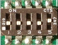
Configuration switches
- Switch 1
- ON : Output voltage is 19V
- OFF: Output voltage is 12V
- Switch 2
- Reserved
- Switch 3
- Reserved
- Switch 4
- Reserved
- Switch 5
- ON : Switch to Bootloader mode
- OFF: Switch to Firmware mode
Switching between the two available output voltages must be done with the device powered off.
NUC and OS Settings
- NUC related settings
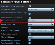
- Setting up the NUC's behavior when power is re-applied:
- - press F2 key during the boot sequence to entering the NUC's BIOS (Visual BIOS 2.0)
- - first click on Advanced then click on Power menu button
- - in Secondary Power Settings section select Power On option for After Power Failure
- - the picture shows the right option in a red framework
- - now the power supply should be able to START the NUC by applying corresponding voltage to its power input
- OS related settings
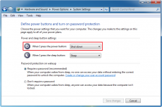
- Setting up the Windows 7 Power Button behavior:
- - from Control Panel select Power Options then on the left pane select Choose what the power buttons do (or do: Control Panel\Hardware and Sound\Power Options\System Settings)
- - then at Power and sleep button settings select Shut down option for power button
- - the picture shows the right option in a red framework
- - now the power supply should be able to STOP the OS (and thus the NUC too) by sending a shut down command via USB
Note: CONFIG1 parameter bit4 field should be set to "1" (see Parameter List)
Bootloader Mode
It is recommended that you only connect USB power to the device
when making a firmware update via “bootloader mode”.
There are two ways to enter in bootloader mode: 1a) or 1b).
1a) Slide the SW1 DIP switch button 1 in ON position.
1b) Press the Switch to bootloader button on the configuration software's user interface.
2) Start the HIDBootloader v2.9j.exe software provided to flash the new firmware.
3) Press File->Import Firmware Image
4) Press Open new Hex File
5) Press Program->Erase/Program/Verify Device
6) If used option 1a) slide the SW1 DIP switch button 1 in OFF position, else skip this step.
7) Press Program->Reset Device
8) After the device reconnects on USB with the configuration software the new firmware version will be displayed in the title bar of the software.
Blink modes
Deep Sleep
2 fast blinks and a pause, repeated every 5s
Low energy state,used in AUTOMOTIVE mode
Initial delay or USB only mode
3 fast blinks and a pause, repeated every 750ms
Signals the Initial Delay, before conditions are met for startup or if the unit is only USB powered
Output ON
Led is allways ON, signals the Output is ON
OffDelay
Led is blinking every 2 sec,ON for 1 sec, OFF for 1 sec
In AUTOMOTIVE mode, signals the period between Ignition is OFF and the Motherboard OFF pulse is sent, see IGN_OFF_TO_MOB_PULSE_OFF_TOUT parameter
HardwareOff Delay
Led is blinking 3 times during a 2 sec period
In AUTOMOTIVE mode, signals the period between Motherboard OFF pulse is sent and Output is turned OFF, see HARD_OFF_TOUT parameter
Characteristics
Minimum Input Operating voltage
Maximum input Operating voltage
Sleep mode Current Consumption
Storage and operating temperature
MTBF
Input connectors
Output Connector
6V
48V
1mA
-40oC to +85oC (storage), -40oC to +65oC (operating)
50K Hrs @ 85oC, >= 200K Hrs at 65oC (projected)
Mini-Fit JR
Mini-Fit JR
Output/Input Rail Output Current (buck/boost converter)
Maximum input current: 5A
Peak Input current: 6A(<30 seconds)
Maximum output current: 5A (input current dependent)
Peak output Current: 6A(<30 seconds @48V input)
NOTE:
When operating at high voltage (input or output) or/or operating at elevated temperatures
de-rating up to 30% might be necessary, forced ventilation required.
For long life operation, please ensure that hottest component on-board is kept below 65C.
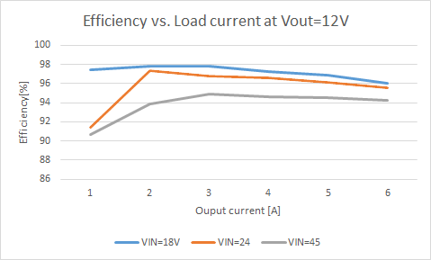
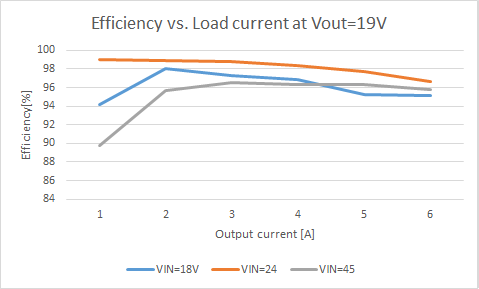
Efficiency Measurements (voltages measured at input/output connectors)
Support and warranty
Standard Hardware Warranty 1Year / US, 2 Year EU.
Parameter List
| NAME | Description |
|---|---|
| NUCMODE[-] | 0-Dumb mode (DUMB) 1-Automotive mode (AUTOMOTIVE) |
| INIT_TOUT[ms] |
When all power supply start-up conditions are met, the PSU will wait this time before continuing with the start-up sequence. |
| VIN_MIN_STARTUP[mV] |
If the input voltage is beyond this threshold and all other start-up conditions are met, the PSU can start. |
| VIN_MIN_RUNNING[mV] |
Instantly turn off the PSU if the input voltage is below this threshold. |
| VIN_MAX_SHUTDOWN[mV] |
If the input voltage is below this threshold and all other start-up conditions are met, the PSU can start. |
| VIN_MIN_DEEP_DISCHARGE[mV] |
If input voltage is below this threshold during IGN_OFF_TO_MOB_PULSE_OFF_TOUT then shutdown sequence will be initiated immediately. |
| VIN_COUNT[ms] |
Input voltage filtering |
| IGN_COUNT[ms] |
Ignition voltage filtering |
| IGN_HIGH_THRESHOLD[mV] |
If ignition voltage is beyond this threshold, ignition is considered to be ON. |
| IGN_LOW_THRESHOLD[mV] |
If ignition voltage is below this threshold, ignition is considered to be OFF. |
| IGN_ON_TO_OUTPUT_ON_TOUT[s] |
After ignition is considered ON, the PSU will wait this time before the output is turned ON. |
| THUMP_TOUT[s] |
After the output is turned ON, the PSU will wait this time before the THUMP output gets enabled. This setting is only valid in automotive mode. |
| MOB_PULSE_TOUT[ms] |
After the output is turned ON, the PSU will wait this time before sending the start-up pulse to the motherboard. |
| MOB_PULSE_WIDTH[ms] |
The length of the start-up/shutdown pulse sent to the motherboard. |
| IGN_CANCEL_TOUT[s] |
After the motherboard boots up, the ignition voltage sensing will be disabled for this period. |
| IGN_OFF_TO_MOB_PULSE_OFF_TOUT[s] |
If ignition is considered to be OFF, the PSU will wait this time before sending the shutdown pulse to the motherboard. |
| HARD_OFF_TOUT[s] |
After the shutdown pulse is sent to the motherboard, the PSU will wait this time before the output is turned OFF. |
| IOUT_LIMIT[mA] |
Output current limit setting. Resolution is 1280mA, minimum setting is 560mA. |
| PWM_SPREAD_MODULATING_PERIOD[ms] |
Modulation period parameter of the Random Spread Frequency Modulation module (used for EMI reduction purposes) |
| PWM_SPREAD_PERCENT[%] |
Frequency deviation parameter of the Random Spread Frequency Modulation module (used for EMI reduction purposes) |
| PWM_FREQ[kHz] |
Operating frequency of the Switched Mode Power Supply. Default 300kHz |
| CONFIG1[bit7..bit0] |
Configuration register. Used for enabling/disabling modules. 0 - disabled, 1 - enabled |
| CONFIG2[bit7..bit0] |
Configuration register. Used for enabling disabling modules. 0 - disabled, 1 - enabled |
| POUT_HIGH_THRESHOLD[mW] |
If output power measured is higher than this threshold the connected motherboard is considered to be ON. |
| POUT_LOW_THRESHOLD[mW] |
If output power measured is lower than this threshold the connected motherboard is considered to be OFF. |
| WRITE_COUNT[count] |
The number of times the internal Flash program memory has been written. |
Software manual
Windows OS built-in support
The DCDC-NUC implements one generic USB class (USB HID), therefore most of the operating systems are recognizing it without any additional driver installation.
Configuration Software
The configuration software provides interface for DCDC-NUC monitoring, logging and setup.
It's recommended to be used by users with deeper understanding of the DCDC-NUC hardware since permits setting voltages, currents and other parameters which can be
dangerous if they are set without precaution.
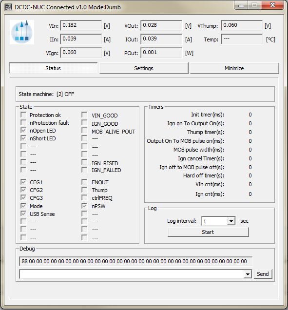
The configuration software has two main screens (Status and Settings) and a header with the important voltage/current values.
The first main screen is the "Status"
Example of this screen is shown in the next image:
The title bar shows the connection status, the firmware version and the mode of the DCDC-NUC. Example: "DCDC-NUC Connected v1.0 Mode: Dumb"
The header of the status screen contains:
- VIn: Input Voltage
- VOut: Output Voltage
- VThump: Thump Voltage
- IIn: Input Current
- IOut: Output Current
- Temp: Temperature
- VIgn: Ignition Voltage
- POut: Output Power
The "Status" screen contains extended information about the current state of the DCDC-NUC like internal state machine, voltages, currents, temperature, different read only state flags. The user also have the possibility to log the current state into a *.csv file in the "Log" section. The "Debug" section is for debug/support and can change between different firmware versions.
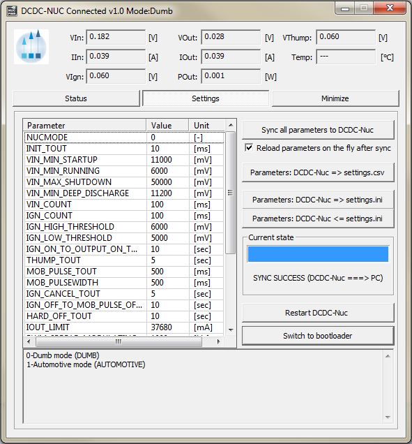
The second main screen is the "Settings"
Example of this screen is shown in the next image:
This screen contains two main sections: the individual parameter setup for experienced users and the parameter save/load into/from file section.
The main section of the "Settings" screen is the individual parameter settings.
This is recommended to be done only by experienced users. Any parameter of the DCDC-NUC can be set from here.
Changing one parameter is simple:
- - select the desired parameter from the "Parameter" list (simple click to select, double-click to edit). Below the parameter list a helper text is displayed (same from this manual).
- - after double click introduce the new value in the new popup dialog and press OK
- - the introduced value is checked - if something is wrong (out of limit, bad value etc.) error message will be shown
- - the ! sign will blink on the "Sync all parameters to the DCDC-Nuc" button to show edited but not saved/synced variables
- - after You have done with all parameter setting press the "Sync all parameters to the DCDC-Nuc" button to send all values to the DCDC-Nuc. IMPORTANT: without this step the new values will be lost, nothing is sent to the DCDC-NUC!
IMPORTANT: any parameter setting is taken into account by the DCDC-NUC in this cases:
- - after a full restart either with power cut from all sources (usb, vin)
- - hitting the "Restart DCDC-Nuc" button
- - keeping the "Reload parameters on the fly after sync" checked.
Do any parameter change with precaution, check the parameters and wires before applying it!
For users who need to setup more devices with the same DCDC-NUC settings, it is recommended to use the save/load parameters buttons. The "Parameters: DCDC-Nuc ===> File (settings.ini)" button loads a full configuration from the DCDC-Nuc and saves it to the settings.ini file. You can disconnect the current DCDC-Nuc from the USB and insert a new one, than press the "Parameters: DCDC-Nuc <=== File (settings.ini)" button to send the last saved configuration into the new DCDC-Nuc.
The "Parameters: DCDC-Nuc ===> CSV File (settings.csv)" button loads all parameters from the connected DCDC-NUC and saves it into a csv file. This type of file can be opened by any spreadsheet editor (OpenOffice, Microsoft Excel etc.) and contains the full set of parameters in human readable form.
The "Switch to bootloader" button is intended to be used for firmware updates. After You press this button the DCDC-NUC will disconnect, it will switch to bootloader mode and firmware can be updated as described here
Every save/load/sync operation on the "Settings" screen affects the progress bar and the status bar on the bottom of the screen (labelled with "State:"). In rare cases You might get error here with "try again" message. This happens in case of one parameter byte get's corrupted or timeout occurs during USB communication and/or DCDC-NUC flashing operation. Please try again and contact our support team only if the device gives this error 4-5 times in a row.
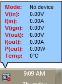
Windows System monitor
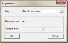
The system monitor is a tray bar software which shows the current state on the tray bar icon and a semi transparent "always on top" capable small window.
The popup window can be moved anywhere on the screen and can be customized. Our current setup has two skins but any combination is possible playing with the
"skin*.mbs" files installed together with this application. The current skin can be selected right clicking on the try icon.
The "skin*.mbs" files are simple text ones editable with any text editor (notepad for example).
Adding a new skin is pretty simple – make a skin1.mbs (use the existing skin0.mbs for starting content) and start playing with the values from the new
file.
The values are self explanatory – skin name, background image files, font descriptions and label/value pair coordinates for all the important DCDC-NUC values.
The size of the popup is defined by the background image – transparent parts can be defined as well (see for example: "bubble1.bmp").
Example screenshots:
Right clicking on the tray icon will pop-up a simple menu:
From which You can see firmware version and state of the DCDC-Nuc from the properties and set some visual parameters of the application (transparency, skin) from Skin:
For auto start with the system make a shortcut of AppTray.exe from the standalone package in the system Startup (Windows 7, Windows 8).
Download software
| Version | Change list |
| 1.0 | First version |
| 1.0.0.1 | Bugfix (MOB_PULSEWIDTH and INIT_TOUT max value risen to 2550) |
Developer manual
Mini-box.com provides one DCDC-Nuc API in a DLL (NUCLib.dll) and examples in Visual C++, Visual Basic and Visual C#.
Basic C++/Visual Basic/C# knowledge is needed to use this examples together with the API.
The API dll has manifest embedded to permit C# and Visual Basic dynamic load.
The API has a set of functions exported to access the full functionality of the DCDC-NUC.
This functions are:
- extern "C" NUCLIB_API unsigned char nucOpenDeviceHandler(unsigned int timer);//open device handler. timer sets the refresh period in miliseconds (4 messages will be sent in this period). IMPORTANT: the handler can be kept open to notice any DCDC-NUC plugged in
- extern "C" NUCLIB_API void nucCloseDeviceHandler();//close device handler
- extern "C" NUCLIB_API void getNUCDevicePath(char* path);//Get opened device path @param path - recommended length 1024, will return empty string if no device opened
- extern "C" NUCLIB_API unsigned char isNUCConnected();//0=not connected, 1=normal state,2=loading settings from device,3=saving settings from pc,4=saving settings from file
- extern "C" NUCLIB_API unsigned char getNUCMode();//get DCDC-NUC mode: 0=Dumb, 1=Automotive
- extern "C" NUCLIB_API unsigned int getNUCInputFlags();//get DCDC-NUC input flags
- extern "C" NUCLIB_API unsigned int getNUCOutputFlags();//get DCDC-NUC output flags
- extern "C" NUCLIB_API float getNUCVIn();//get DCDC-NUC Input Voltage
- extern "C" NUCLIB_API float getNUCIIn();//get DCDC-NUC Input Current
- extern "C" NUCLIB_API float getNUCVOut();//get DCDC-NUC Output voltage
- extern "C" NUCLIB_API float getNUCIOut();//get DCDC-NUC Output Current
- extern "C" NUCLIB_API float getNUCTemperature();//get DCDC-NUC temperature - 1000 deg C is invalid value (output not enabled)
- extern "C" NUCLIB_API float getNUCVIgnition();//get DCDC-NUC Ignition Voltage
- extern "C" NUCLIB_API float getNUCPOut();//get DCDC-NUC Output Power
- extern "C" NUCLIB_API float getNUCVThump();//get DCDC-NUC Thump Voltage
- extern "C" NUCLIB_API unsigned char getNUCVerMajor();//get DCDC-NUC major version of the firmware
- extern "C" NUCLIB_API unsigned char getNUCVerMinor();//get DCDC-NUC minor version of the firmware
- extern "C" NUCLIB_API unsigned char getNUCDbgByte(int i);//get DCDC-NUC debug bytes
- extern "C" NUCLIB_API unsigned int getNUCTimer(unsigned int cnt);//get DCDC-NUC timer
- extern "C" NUCLIB_API unsigned int getNUCStateMachine();//get DCDC-NUC internal state machine
- extern "C" NUCLIB_API void restartNUC();//restart DCDC-NUC
- extern "C" NUCLIB_API void restartNUCInBootloaderMode();//restart DCDC-NUC in bootloader mode
- extern "C" NUCLIB_API void setNUCCommand1Byte(unsigned char command, unsigned char value);//DCDC-NUC direct commands (for debugging)
- extern "C" NUCLIB_API void setNUCCommand2Byte(unsigned char command, unsigned int value);//DCDC-NUC direct commands (for debugging)
- extern "C" NUCLIB_API void setNUCCommandBuffer(int len, unsigned char* values);//DCDC-NUC direct commands (for debugging)
- extern "C" NUCLIB_API unsigned int getNUCMaxVariableCnt();//get DCDC-NUC maximum variable count
- extern "C" NUCLIB_API unsigned char getNUCVariableData(unsigned int cnt, char* name, char* value, char* unit, char* comment);//get DCDC-NUC variable data
- extern "C" NUCLIB_API void startNUCLoadingSettings(unsigned char to_file, unsigned char compare_with_old);//start loading data from device
- extern "C" NUCLIB_API unsigned char getNUCLoadingSettingsState();//get load settings current state: 0-64 - steps, 100=success, 0xF1-0xFF=failure
- extern "C" NUCLIB_API unsigned char setNUCVariableData(unsigned int cnt, char* value);//set DCDC-NUC variable data for a given variable
- extern "C" NUCLIB_API void startNUCSaveSettings(unsigned char from_file);//start saving data to device
- extern "C" NUCLIB_API unsigned char getNUCSaveSettingsState();//get saving current state: 0-64 - steps, 100=success, 0xF1-0xFF=failure
See the examples for usage.
IMPORTANT: the API dll needs 4 files from Visual Studio 2005 redistribution pack (Microsoft.VC80.CRT.manifest, msvcm80.dll, msvcp80.dll, msvcr80.dll).
IMPORTANT: the API supports only one DCDC-NUC connected to the computer.
Visual C++ Example
Open DCDCNUCTestAPI.sln from the package, set CLibTest project as active project, run it and see CLibTest.cpp for usage example.
Visual Basic Example
Open DCDCNUCTestAPI.sln from the package, set VBLibTest project as active project, run it and see Module1.vb for usage example.
Visual C# Example
Open DCDCNUCTestAPI.sln from the package, set CSLibTest project as active project, run it and see Program.cs for usage example.
Download API and example projects
| Version | Change list |
| 1.0 | First version |
| 1.0.0.1 | Bugfix (MOB_PULSEWIDTH and INIT_TOUT max value risen to 2550) |
